|
|||||
|
|||||
|
|
|||||
|
|||||
|
|
Term
|
Definition and Discussion
|
|
The Admin Info button appears on a Task's configuration dialog or Data Presentation dialog when the Task is recalled from a DataSet Archive or executed under QuikLook. Clicking the button opens a subdialog that gives pertinent information regarding Vision, the Vision driver, the Precision Tester, the User's host computer and a variety of other parameters. The nature of the dialog will depend on the type of Task that is presenting the information. A simple Program Control Task will show a reduced dialog with only basic information. A Hardware or Measurement Task will show a larger dialog with more Precision tester detail.
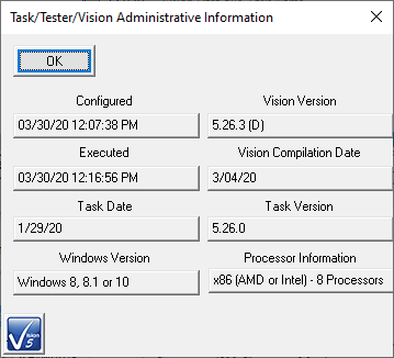 Branch Task Admin Info Dialog.
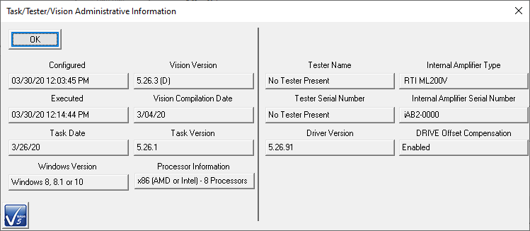 Hysteresis Task Admin Info Dialog.
| |
|
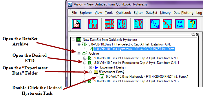
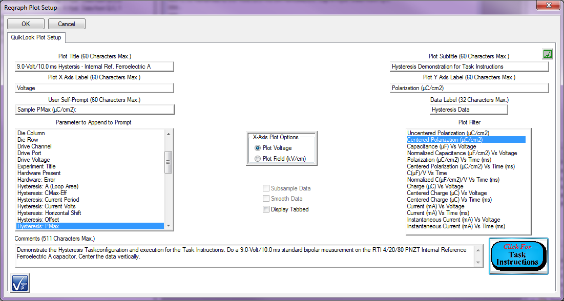
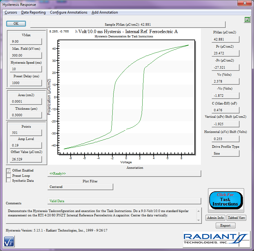
Archive Regraph refers to the action of recalling a Task from a DataSet Archive for configuration and, possibly, data review.
The figures show the procedure for an archived Hysteresis Task.
    | |
|
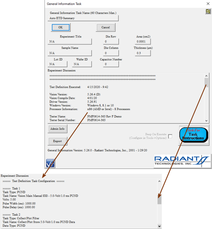
This is a General Information Task that is automatically added by Vision to an Executed Test Definition (ETD) as the first-executed Task. It contains a summary of the configuration of every Task in the Test Definition.
 | |
|
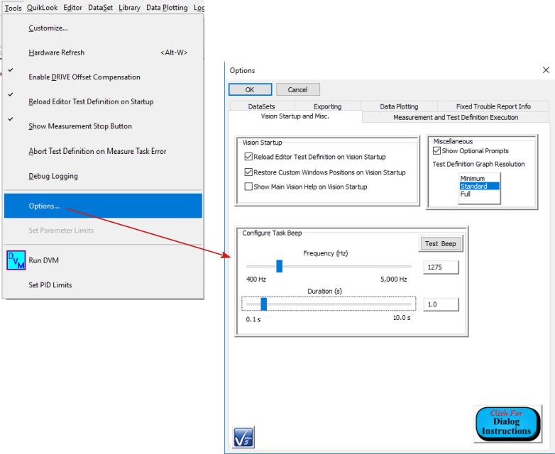
All Tasks now have a Beep On Execute check box added to their configuration dialogs. This control is absent on QuikLook configuration dialogs. This control will normally be unchecked. When checked, the Task will emit an audible beep when it executes in a Test Definition. This serves as an announcement to the human operator that that Task is executing.
The duration and pitch of the beep is configured globally in "Tools->Options...->Vision Startup and Misc.".
 | |
|
This term refers to the act of returning Test Definition execution to a previous Branch Target Task, by a Branch Task, based on the current status of a Branch Logic Condition. This tool allows a Test Definition, or a subsequence of Tasks in a Test Definition, to be repeatedly executed in a single Test Definition Execution.
| |
|
This is a comparison between the current state of a selected User Variable and a fixed value of the User Variable type (integer, real, text or Boolean), using a fixed comparator (less than, less than or equal to, equal to, greater than, etc.) The results of this comparison will be used by a Branch Task or a Nesting Branch Task to determine if Test Definition execution is to be returned to the associated Branch Target/Nesting Branch Target Task or to be passed to the Task following the Branch/Nesting Branch in the Test Definition.
| |
|
This is any single Task with which a subsequent Branch Task has been associated and to which the Branch Task will return Test Definition execution if the Branch Logic Condition is met.
| |
|
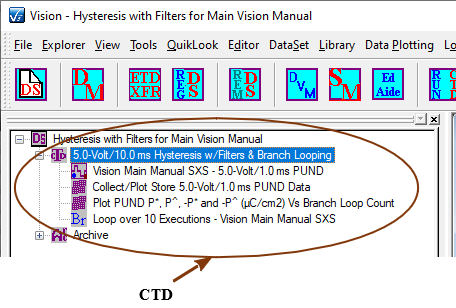
60 characters maximum. This is the descriptive name associated with a DataSet's Current Test Definition (CTD). This name should be descriptive of the CTD and should be unique. As the CTD is executed in the DataSet, the execution will be archived as an Executed Test Definition (ETD) using this name as a basis. The ETD name recorded in the DataSet Archive will be this text augmented with a serialized index to render the ETD name unique. This name is offered for editing when a Test Definition is moved from the EDITOR into the DataSet's CTD. It may also be immediately edited by double-clicking.
 | |
|
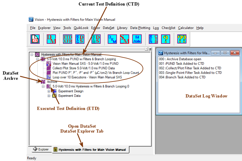
This is the top-most structure in a DataSet. It is a single Test Definition that is ready for immediate execution. The CTD consists of a CTD Name and the list of Tasks that make up the Test Definition. Running the Test Definition by clicking <F1> or selecting "DataSet->Execute Current Test Definition (CTD)" will cause the Tasks in the CTD to execute. After complete execution the Tasks are written as Executed Test Definitions to the DataSet Archive using the CTD Name as basis and appending a serialized index to form the ETD Name.
 | |
|
Although Vision and its associated Tasks are distributed free to anyone, a number of Tasks are grouped together into Custom Task Suites that must be purchased and licensed with a Security.Sec file. These Tasks are also freely distributed with Vision. Anyone can open a Custom Task to review the configuration dialog and access the Tasks Instructions. Anyone can review data that are captured by a Task in a Custom Task Suite. However, in order to include a Custom Task in a Test Definition or to operate the Task it must be licensed.
Custom Task Suites include:
| |
|
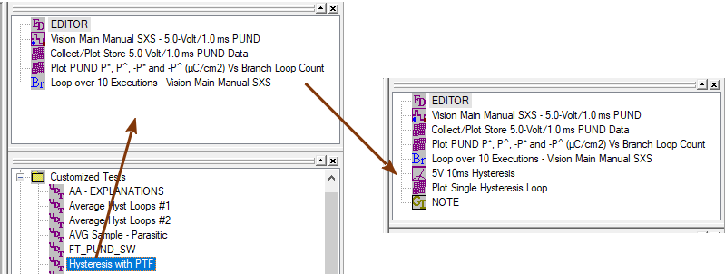
A Customized Test is an entry in the TASK LIBRARY under the "Customized Tests" folder. It appears to be a Task in the folder, but actually represents a complete Test Definition that has been configured in the EDITOR and moved into the TASK LIBRARY as a single entity. The Customized Test contains all Tasks in the Test Definition with configured values as they were established in the EDITOR. Moving the Customized Test back into the EDITOR does not open any configuration dialogs. However, the Tasks in the Customized Test are appended, as configured, to any Tasks already in the EDITOR Test Definition.
 | |
|
Data Mining is a tool that allows any subset of data-collecting Tasks of a specific type to be collected from any number of source DataSets and written together to a single ETD in a single DataSet Archive in a new or existing DataSet. In addition a single Filter, of any type that is appropriate to the type of the Tasks being mined, can be configured to collect, operate on, plot and store the data of the Tasks being mined.
| |
|
A DataSet is a fundamental data management tool in Vision. It might be considered Vision's laboratory notebook. A DataSet consists of a Test Definition (or experiment) that is ready to executed, known as the Current Test Definition (CTD). It also contains the DataSet Archive that holds the complete record of Test Definitions executed within the DataSet. These are known as Executed Test Definitions (ETDs).
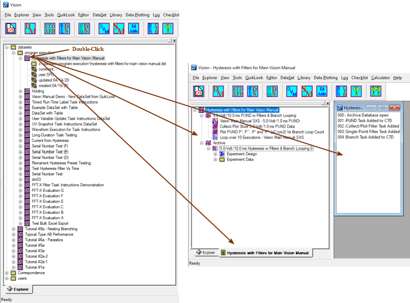
DataSets may be registered to Vision or unregistered to keep Vision as clean as possible. Registered DataSet are listed, by file location, in the DataSet Explorer tree. Double-clicking a DataSet in the tree opens the DataSet in its own tab in the DataSet Explorer window. Any number of DataSets may be opened in Vision/the DataSet Explorer.
When open, a DataSet has the following components:
In addition a DataSet has the following properties:
 Note that, despite the opportunity to configure and execute Tasks from the QuikLook menu, Vision is designed to have experiments performed by executing them as Test Definitions in DataSets.
| |
|
This is the DataSet component that appears immediately below the Current Test Definition (CTD) in an open DataSet tree. This is the repository for all previous activity performed within the DataSet. It forms a collection of one or more Executed Test Definitions (ETDs)
| |
|
This is a primary Vision program window. By default it occupies the entire vertical expanse of the left side of the main Vision program User Interface (UI). The DataSet Explorer contains a tree that represents the file folder tree containing every registered DataSet. Each DataSet is represented by an icon in the tree at the position at which the DataSet file is located in the Vision host file system.
Each DataSet is represented by an icon and the DataSet name in the tree. The DataSet representation can be opened to display DataSet File Path and Name, Comments (if any), Experimenter Initials, update date and creation date. Double-clicking the DataSet name/icon will open the DataSet in a new tab in the DataSet Explorer.
 | |
|
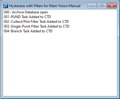
This is a text window that appears in the Vision User Area when a DataSet is opened in the DataSet Explorer. The log window maintains a chronological record of activities in the DataSet as they occur. The text is searchable and can be saved to file and/or printed. This text record has proven to be of limited value. By default, the text is cleared each time the DataSet is closed. This default setting can be adjusted under the Vision "Log" menu.
The Log window also offer some control over the DataSet. This window must be the top-most window in the User Area to execute the DataSet CTD or perform other actions. Closing the log window is the preferred method of closing the DataSet.
 | |
|
This is a BNC port at the front and rear panel of all Precision testers. The DRIVE port is normally connected to one electrode of the Device-Under-Test (DUT). The RETURN port is connected to the opposite electrode. The DRIVE port applies a DRIVE stimulus voltage to the sample electrode to stimulate a sample Charge (µC) response at the opposite electrodes. The DRIVE stimulus voltage is specified by the execution of a Task in the Vision program based on the experimenter's configuration of the Task.
Note that the front-panel and rear-panel DRIVE BNC ports are electrically identical and either port may be used to contact the DUT.
With the DRIVE connected directly to the DUT electrode, a maximum of ±500.0 Volts may be applied depending on the specifications and limits of the tester's internal amplifier. For high-voltage measurements greater than ±500.0 Volts, DRIVE is not connected directly to sample. Instead it is connected to a High-Voltage Amplifier (HVA) through a Radiant Technologies High-Voltage Interface (HVI). It serves as a low-voltage signal into the HVA that is amplified to produce the high-voltage output that is then connected to the sample electrode through the HVI. With an HVI/HVA present, Vision allows voltages of up to ±10,000.0 Volts.
| |
|
This is a primary Vision program window. It is located, by default, at the top of the right-hand column of windows, just above the TASK LIBRARY.
Test Definitions are designed and constructed in this window for execution in DataSets. Tasks are moved from the TASK LIBRARY into the Editor to append them to any Tasks already in the Editor and add them to the Test Definition. When a Task is moved into the Editor, its configuration dialog is opened to allow the Task to be programmed for use in the Test Definition. A Task may be reopened for configuration review and/or adjustment by double-clicking it in the Editor.
The EDITOR window has a limited set of operations that may be performed on the Test Definition being constructed, normally by right-clicking in the EDITOR Window or by using Vision hot keys:
The EDITOR is not a completely general tool. Because of dependencies between some Tasks in the EDITOR, the following operations cannot be directly performed in the EDITOR:
The Editor Aide tool is provided to help completely generalize EDITOR operations.
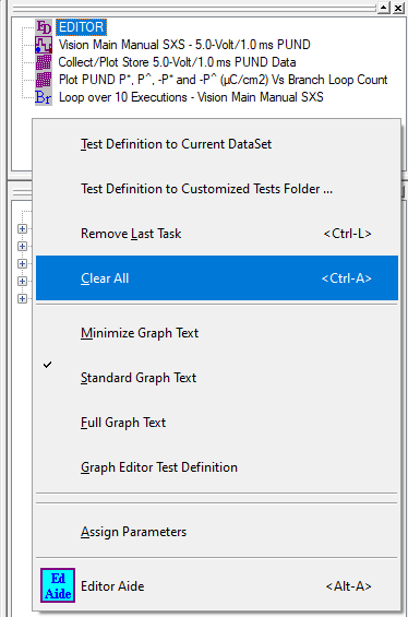 EDITOR Window and Right-Click Menu Options.
| |
|
This tool allows any number of Executed Test Definitions (ETDs) to be copied sequentially from any number of source DataSets to a single new or existing DataSet Archive.
| |
|
The Editor Aide provides a set of tools that allow Test Definition editing to become completely general. In addition to standard EDITOR tools, the Editor Aide allows:
In addition, the Editor Aide allows a Test Definition to be stored out to or recovered from a permanent file.
Under normal operations, a Test Definition is moved into the Editor Aide from the EDITOR. Then it is adjusted appropriately and moved back to the EDITOR, with an option to clear the EDITOR of existing Tasks before returning the Test Definition. Tasks in the Editor Aide may have some basic parameters assigned. These include Task Name, Comments and, where appropriate, Sample Area (cm2), Sample Thickness (µm) and Max. Voltage. As the Tasks in the Editor Aide are moved back to the EDITOR, their configuration dialogs are opened for review, update or initial configuraiton.
| |
|
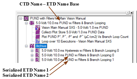
Each Executed Test Definition (ETD) is stored to a DataSet Archive under a unique identifier known as the ETD Name. The ETD Name has the CTD Name as its base. It is made unique by appending a serialized index. The ETD Name is an important element. If an ETD Note, or alternative icon is associated with a specific ETD, the association is made through the ETD Name.
 | |
|
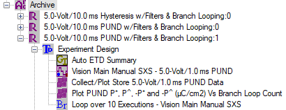
An Executed Test Definition (ETD) is the record under the DataSet Archive of a single full execution of a DataSet Current Test Definition (CTD). The ETD is recorded in the Archive by ETD Name. The ETD Name takes the CTD Name of the Test Definition that was executed to create the ETD as a base. It serializes the name to make it unique.
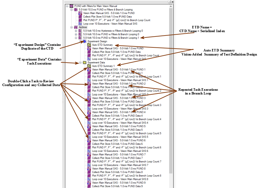
The ETD contains two subfolders:
NOTE: The Task list in the "Experiment Data" folder can differ significantly from the list in the "Experiment Design" folder. Two main factors can contribute to this difference: repeated Task execution in a Branch Loop or early Test Definition termination using an Exit Task. An If/Then Task and Endif Task structure can also cause segments of Task in the Test Definition design to be omitted from execution.
NOTE: Both the Experiment Design and Experiment Data folders will show an initial Task called "Auto ETD Summary" that was automatically inserted by Vision. See the link for details.
 | |
|
Experiment Data is a standard folder, under each Executed Test Definition (ETD) in the DataSet Archive, that contains the results of each Task executed when the Current Test Definition (CTD) was run. Note that the number, and possibly sequence, of Task entries in this folder will frequently differ from the Task sequence in the CTD. This can be the result of repeated execution of Tasks in a Branch Loop, early Test Definition termination using an Exit Task or skipping sequences of Tasks using an If/Then and Endif Task structure.
Tasks in the Experiment Data folder can be opened to recall Task configuration and collected data, for Tasks that collect data (Measurement Tasks, Filters)
 | |
|
Experiment Design is a standard folder under under each Executed Test Definition (ETD) in the DataSet Archive. The folder contains an exact duplicate of the Current Test Definition (CTD) that was executed to generate the ETD. The folder also includes and initial Auto ETD Summary, added by Vision. The Experiment Design folder is used by Vision when the ETD is copied back into the CTD, the EDITOR or a Customized Test.
 | |
|
All Tasks have the capability to have their configuration parameters and, for data-collecting Tasks, collected data exported to an external target. Targets include:
Data-collecting Tasks can also export to a Vision Data File (VDF/*.vis). In addition, data-collecting Tasks can have their plotted data image exported to a Windows Meta File, JPEG File or Bitmap File.
Exporting is available on a Tasks main configuration dialog when the Task is recalled from a DataSet Archive. For Measurement Tasks, exporting is accessed through the Data Presentation dialog. Measurement Tasks can also export data from a Data Presentation dialog that appears a the result of a QuikLook execution.
Note that most exporting is deferred until all Task dialogs have been closed. Measurement Tasks that are configured to export the plotted data to an image file will have the image exported immediately after the export is configured.
| |
These represent a very generalized list of functionality. Many varieties of Filters exist. Not all match this list. Please see the Task Instructions for individual Filter Tasks under TASK LIBRARY->Filters.
| |
|
The General Purpose Interface Bus is an 8-bit parallel instrument communication bus developed by Hewlett-Packard. It has been an industry standard equipment communication bus. Recently it has become supplanted by the Universal Serial Bus (USB), but is still widely supported.
Originally Vision communicated with external instruments - normally thermal controllers - only through the GPIB bus. GPIB<->Serial converters were required for serial devices. Later Vision began accommodating RS232/RS485 instruments directly. And now Vision will communicate with an instrument through any bus required provided the instrument manufacturer supports third-party control. However, Vision's original support for GPIB remains in place.
| |
|
Any time the hardware status changes while Vision is being run, Vision must be informed of the change by doing a Hardware Refresh. For example, if a High-Voltage Interface (HVI) or CS 2.5 Current Source is turned off or on, the Vision must be refreshed to detect the status change. A Hardware Refresh is performed by selecting "Tools->Hardware Refresh" or (more commonly) pressing <Alt-W>.
| |
|
In general, Hardware Tasks are Tasks that communicate with the Precision tester and cause the tester to operate on a Device-Under-Test connected between the tester DRIVE and RETURN ports. The Hardware Task will specify the DRIVE voltage signal that is to be applied to the sample by the tester on Task execution.
Hardware Tasks may also refer to Tasks that operate devices other than the Precision tester. Such devices may be manufactured by Radiant Technologies, Inc. or other manufacturers. These include, but are not limited to:
Most Hardware Tasks are found both in the TASK LIBRARY and in QuikLook. A few Hardware Tasks, including Tester Information and Accessory EEPROM, are found only in QuikLook.
| |
|
A High-Voltage Amplifier (HVA) is an instrument that takes a low-voltage (DRIVE) input signal and amplifies it to produce a high-voltage output. HVAs are built by manufacturers other than Radiant Technologies. (Most HVAs associated with the RTI Precision tester family are manufactured by Trek. ) HVAs are connected to Precision testers through a High-Voltage Interface (HVI) manufactured by Radiant Technologies, Inc. With an HVI/HVA pair connected to the Precision tester, the maximum DRIVE voltage is boosted from ±500.0 Volts to ±10,000.0 Volts.
| |
|
A High-Voltage Interface (HVI) is a safety device places into the DRIVE signal path between a Precision tester and a High-Voltage Amplifier (HVA). In case of sample breakdown under the application of high voltages, the HVI detects a high-voltage signal short between the DRIVE and RETURN and opens the circuit to protect both equipment and human life. An HVI must be present for DRIVE voltages to exceed ±500.0 Volts. With an HVI/HVA pair present, the maximum allowed DRIVE signal is increased to ±10,000.0 Volts.
| |
|
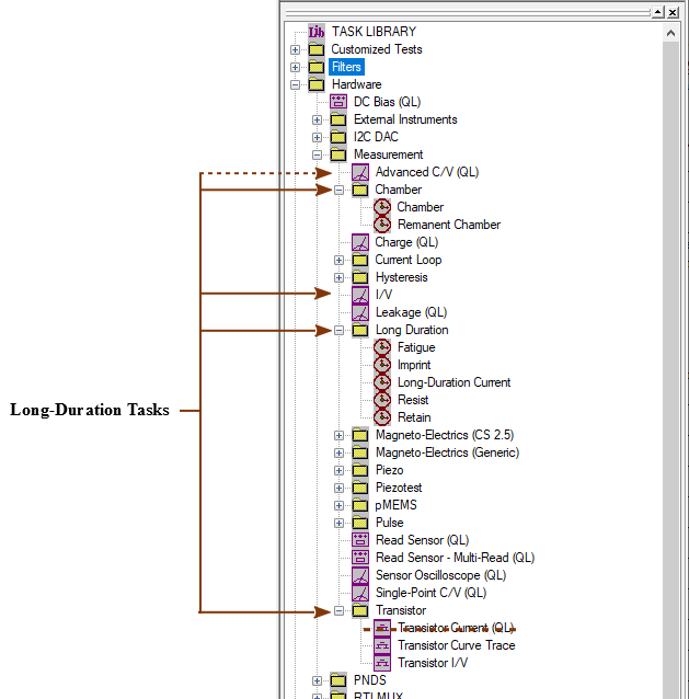
Long-Duration Tasks are Measurement Tasks that continue execution over extended periods - perhaps days. As such, they are unique in two ways:
There are relatively few Long-Duration Tasks. Most, but not all, are found in TASK LIBRARY->Hardware->Measurement->Long Duration. These include:
The Chamber Custom Task Suite consists of the Chamber and Remanent Chamber Tasks found in TASK LIBRARY->Hardware->Measurement->Chamber.
Advanced C/V meets the definition of a Long-Duration Task and does provide runtime data plotting. However, that Task is found under the QuikLook menu. However, its analog, the I/V Task, is not included in QuikLook. Both of these are found in TASK LIBRARY->Hardware->Measurement, without subsubfoklder.
Transistor Current is a simple Tasks that returns a single measured value. It is found in QuikLook. However, the other two Tasks in the Transistor Custom Task Suite use the Transistor Current Tasks to make extended Long-Duration measurements. These are Transistor I/V and Transistor Curve Trace and are found in TASK LIBRARY->Hardware->Measurement->Transistor.
 | |
|
Measurement Tasks are Hardware Tasks that receive measured signal data back from the Precision tester RETURN port. They operate on the data as appropriate and store the data. They may pass data to Filter Tasks for further operation and display.
Most Measurement Tasks are found in both the TASK LIBRARY and in the QuikLook menu. Long-Duration Measurement Tasks do not fit the philosophy of QuikLook and are not found in that menu.
| |
|
No Execute is a check box that has been added to the configuration dialog of every Task. (It is absent in QuikLook configuration dialogs.) When checked, the Task will take no action whatsoever when it is executed in a Test Definition. It will simple write itself to the DataSet Archive and then pass execution to the next Task in the Test Definition. For Tasks that collected data, data vectors and/or parameters will be assigned NULL DATA values that are written to the Archive.
The purpose of the No Execute check box is to allow the Task to be removed from Test Definition execution without physically removing it from the Test Definition. When a Task is executed with No Execute checked, its standard icon will be replaced in the DataSet Archive with
| |
|
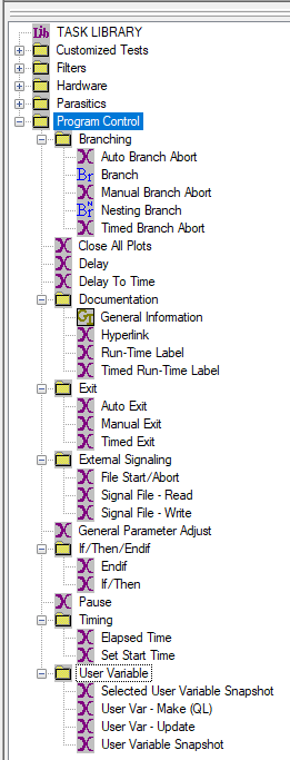
Program Control Tasks do not communicate with the Precision tester or any external device. These are Tasks that control and/or monitor Test Definition sequencing and provide experimental documentation. The Tasks can also be used to control and monitor program timing and to do basic and generic communications with external programs. The Tasks are found under TASK LIBRARY->Program Control. None of these Tasks is found in the QuikLook menu.
 | |
|
QuikLook is a Vision menu that holds a subset of the Hardware Tasks in Vision. These Tasks are available for immediate configuration and execution without the need to include them in a Test Definition or operate them in a DataSet. QuikLook is intended for a quick "Let's-See-What-We've-Got" measurement on a sample or to validate Vision and tester operation. It is not intended to be the primary experimental tool in Vision. It is not intended to store data. (For this reason, Long-Duration Tasks are not included under QuikLook.) Strict QuikLook operation limits Vision to about 3% of its capability. Nevertheless, tools to store data from a QuikLook measurement are available. These include QuikLook-to-DataSet and Exporting.
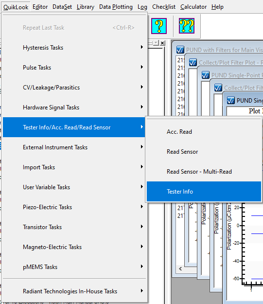
Tasks do not appear directly under the QuikLook menu. Instead they are distributed among categories under the menu. See the Figure.
When the Vision program is started, C:\Program Files (x86)\Radiant Technologies\Vision\System is searched for all *.vlr file. Each *.vlr file represents a Task. Each of these files is loaded into TASK LIBRARY as the program starts. Each Task is also queried to determine if it is to be placed under the QuikLook menu. If so, it is further queried to determine the category and then written to the menu.
The Tester Information Task and Accessory EEPROM Task appear only under the QuikLook menu. These are not available in TASK LIBRARY.
 | |
|
This is a BNC port at the front and rear panel of all Precision testers. The RETURN port is normally connected to one electrode of the Device-Under-Test (DUT). The DRIVE port is connected to the opposite electrode. The RETURN port receives the DUT Charge response (µC) to a voltage stimulus applied by the DRIVE port to the opposite electrode. The DRIVE stimulus voltage is specified by the execution of a Task in the Vision program based on the experimenter's configuration of the Task.
Note that the front-panel and rear-panel RETURN BNC ports are electrically identical and either port may be used to contact the DUT.
With the RETURN connected directly to the DUT electrode, a maximum of ±500.0 Volts may be applied to the DRIVE electrode depending on the specifications and limits of the tester's internal amplifier. For high-voltage measurements greater than ±500.0 Volts, RETURN is not connected directly to sample. Instead it is connected to the DUT through a Radiant Technologies High-Voltage Interface (HVI).
| |
|
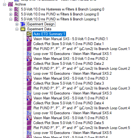
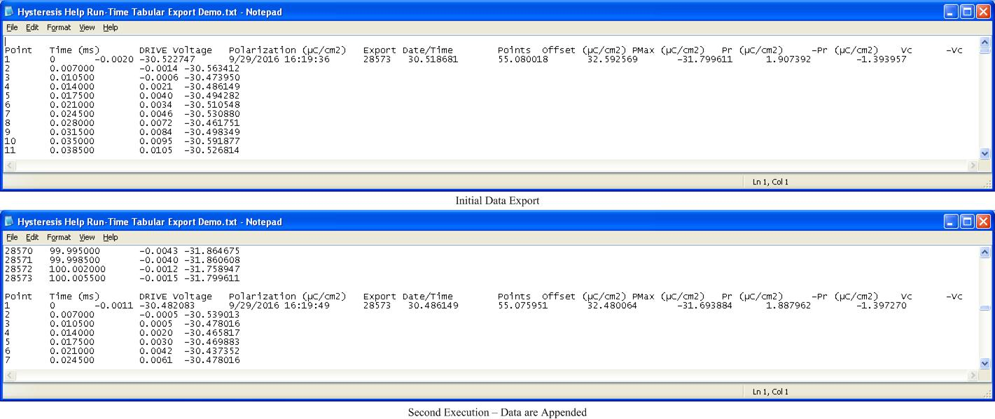
All Tasks are able to export their configuration to a text file. Data-collection Tasks, including Measurement Tasks and Filters, also export their collected data. Such exporting is performed after the Task has completed execution on QuikLook measurement or when the Task is recalled from a DataSet Archive. More recently data-collection Tasks have had the added capability of Runtime Tabular Text Exporting. In this case the Task exports data to a specified text file as the data are collected. Only capture data are exported, under columns with headings. The first data row will also include Single-Point data, if any, and a date/time stamp. Configuration parameters are not exported.
As data are captured they are appended to any data already in the Runtime Tabular text file. In this way the Task may be repeatedly execute - by Branch Looping and/or repeated CTD execution - without having to reconfigure the Task. All data are collected into a single file.
Data are exported in single tab-delimited format. Data may visibly shift left or right relative to column headers or as execution proceeds, when viewed in a text editor. But the data will import correctly into Excel, Origin or other common math or data manipulation program.
The figure shows the output of subsequent executions of the Hysteresis Task.
 | |
|
Security.sec is a license file that enables configuration and execution of the Tasks in one or more Custom Task Suites that must be purchased and licensed. The file is keyed to one or more Custom Task Suites. It is also keyed to a unique code in the EEPROM of the Precision tester for which it was purchased. The file is copied into C:\Program Files (x86)\Radiant Technologies\Vision\System. The file may be copied into any number of Vision host computers. However, it is not transferable between users of multiple Precision testers.
| |
|
The SENSOR 1 and SENSOR 2 ports are BNC ports at the rear panel of the Precision tester. These are voltage input ports in the range ±10.0 Volts. These ports may be independently enabled for synchronous voltage capture simultaneously with the capture of a samples Charge (µC) output in any Measurement Task. Any externally-measured property that is linearly related to an output voltage from the capture device can be measured at these ports, provided the signal is within the ±10.0 Volt limit. Properties such as temperature (°C/F/K), light intensity, pressure, etc. might be measured. Most commonly these ports are used by the Tasks in the Piezoelectric Custom Task Suite to capture displacement.
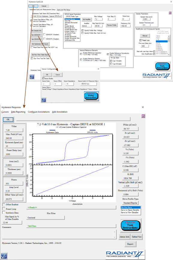
The configuration offers a subdialog in which scale and offset terms, along with a label, may be specified. The label is provided to allow the captured data to be distinguished on a data plot. Scale and offset terms are provided to allow the captured voltage to be converted back into the measured property:
Property = Scale (Property Units/Volt) X Voltage + Offset (Property Units) (1)
[Displacement (µm) = -5.0 (µm/V) X SENSOR 1 Voltage + 0.0 µm]
Note that the SENSOR configuration also allows the output impedance (W) of the measurement device to be specified. However, the input impedance (W) of modern Precision testers is infinite and the impedance (W) of the external device is irrelevant/insignificant. This control should be left at the default value of 50.0 W.
The figure shows a 7.2-Volt/10.0 QuikLook Hysteresis measurement on the 1.0 nF Linear Internal Reference Capacitor. The DRIVE output voltage has been routed to the SENSOR 1 input port and capture is enabled. Sensor Scale is left a the default value of 1.0 X and the Sensor Offset remains at 0.0. The plotted data represent the actual DRIVE voltage.
 | |
|
Single-Point Data refer to sample response that can be expressed as a single integer or real numeric value. The Single-Point data may represent the directly-measured Task response such as a PUND Task P* (µC/cm2) or -P^ (µC/cm2) response. Single-Point data can also refer to single-number data derived from more-complex measured data such as PMax (µC/cm2) or ±Coercive Voltage (Vc) taken by analyzing a complete Hysteresis Polarization (µC/cm2) Vs Voltage (PV or PE) loop.
| |
|
A Task is a semi-independent agent that does the work within the Vision program. Tasks are user-configurable and executable program elements. Each Task performs one complete operation. Tasks may be very simple: Delay Test Definition Execution for a programmed number of seconds. Or Tasks may be very complex: perform a complete Fatigue characterization of the Device-Under-Test (DUT).
Tasks are "semi-independent" because certain Tasks rely on a programmed association with one or more Tasks that precede them in the Test Definition. For example, a Branch Task must be associated with any single preceding Task to which it may return Test Definition execution depending on the Branch Logic Condition. This is known as a Branch Target Task. Likewise, most Filter Tasks require association with one or more preceding Measurement Tasks and/or other Filter Tasks to provide data as input.
Each Task is a Windows Dynamic Link Library with a *.vlr extension and stored in C:\Program Files (x86)\Radiant Technologies\Vision\System. On startup the Vision program searches that file path for every instance of a *.vlr file. (Nearly) all *.vlr files found are opened and inserted into the Vision TASK LIBRARY window tree. If the Task indicates that it is also to be inserted into the QuikLook menu, it is queried for its QuikLook category and inserted into the menu under that category. Note that the Tester Information Task and Accessory EEPROM Task are inserted only into the QuikLook menu.
| |
|
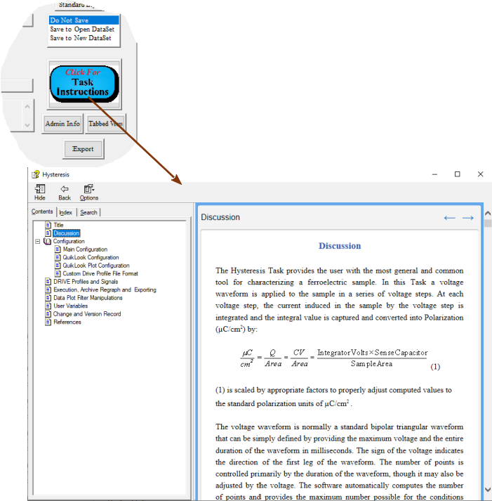
Every Task has an associated *.chm help file known as the Task's Task Instructions. The file is located in C:\Program Files (x86)\Radiant Technologies\Vision\Help. Each *.chm file is specific to the Tasks being documented. The general format of the file is consistent and includes:
The Task Instructions are accessed by clicking the Click For Task Instructions button from any Task dialog. The figure shows the Hysteresis Task Instructions.
 | |
|
The TASK LIBRARY is a primary Vision window. By default it is the middle window, just below the EDITOR window and just above the Document Library, along the right border of the main Vision window. The TASK LIBRARY consists of a tree structure that contains (nearly) every Task available to Vision. Tasks are distributed by category, in the tree, to folders, subfolders and subsubfolders. They will never appear more than three levels deep in the tree.
The TASK LIBRARY is filled, on Vision startup, by searching the file path C:\Program Files (x86)\Radiant Technologies\Vision\System for every instance of a file with a *.vlr extension. Each such file is a Windows Dynamic Link Library (DLL) representing a single Task. Each Task provides Vision the TASK LIBRARY tree location in the form of text defining the folder, subfolder and subsubfolder.
The TASK LIBRARY primarily serves as the access location for Tasks to be moved into the EDITOR to be configured and then appended to the Test Definition that is being constructed in the EDITOR. Tasks that also appear in the QuikLook menu are indicated with " (QL)" appended to their name in the TASK LIBRARY tree. As a secondary function, QuikLook configuration and execution of a QuikLook Tasks can be done from the TASK LIBRARY by double-clicking the Task or by right-clicking and selecting "QuikLook Execute" from the popup menu.
| |
|
A text identifier for every Task in a Test Definition. Tasks are permanently stored in a DataSet Archive under the Task Name. For this reason the Task Name should be unique and meaningful for every Task in the Test definition. A carefully-specified Task Name will allow simpler future identification of archived data. Each Task type has a unique default Task Name that includes an abbreviated label for the type followed by a serialized index to keep the name unique. Although the default Task Name, along with the Task type icon, does allow future identification of the Task by type it does not convey enough information to distinguish the Task's configuration or purpose. This Task element has a 60-character limit.
| |
|
A Test Definition is a linear sequence of Tasks that form an experiment. A Test Definition is constructed and modified in the EDITOR window. It is then moved into a new or existing DataSet Current Test Definition (CTD) for execution and archiving. A Test Definition executes serially by operating each Task in sequence from first (top-most) to last (bottom-most). The serial sequencing of the the Test Definition execution can be modified in one of three ways:
Of these, Branch Looping is very common. The other two are uncommon.
A Test Definition renders Vision a very powerful tool. Properly constructed, the execution of a Test Definition can produce abundant and complex data automatically and very quickly. The cost of this convenience is careful attention to Test Definition construction and design. The Tasks in a Test Definition should be checked and double-checked for both proper parameter setting and for proper documentation (Task Name, Comments, Plot Labels).
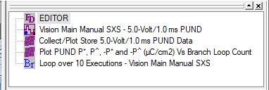 A Test Definition in the EDITOR Window.
| |
|
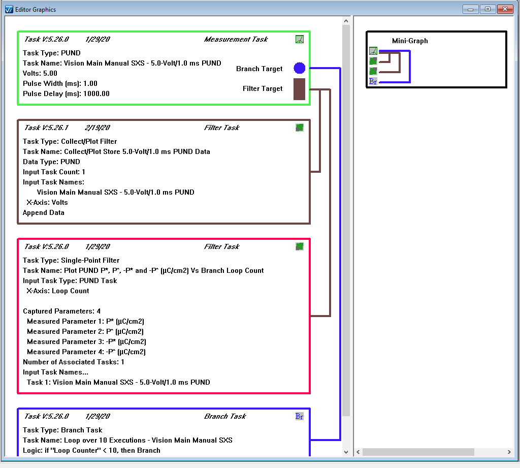
A Test Definition Graph is a split window that shows a graphical representation of a Test Definition in a Windows meta document. In the document, each Task is represented as box. The box has a border represented by the Task type and also shows a Task type icon with Task type text. The text shown in the box is provided by the Task and represents the current Task configuration. The color of the border and the contents of the text can be edited for any text box.
Associations between Tasks are shown as connecting lines and graphical elements in the Task. A blue line connects a Branch Task with its preceding Branch Target. The Branch Target has a blue dot centered along its right-most border. Filters are connected to their input Task(s) using brown lines and the Filter source Task(s) has (have) a brown rectangle at the bottom right of the Task box.
The right half of the Test Definition Graph shows a mini structure with no text. It shows the Task type icons and the linking lines between dependent Tasks.
The entire document can be copied to the clipboard for inclusion in a Word document or other document that recognizes Windows meta document objects.
In the figure the Single-Point Filter Task is highlighted in pink. This indicates that the Task is selected for possible border color and/or text content editing.
 | |
|
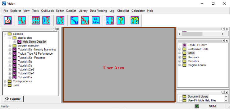
The User Area is the portion of the main Vision window that is not occupied by the menu, the toolbar or any of the standard Vision windows. By default this will be the center of the Vision window. This area is used to place DataSet Log Windows, Filter and Long-Duration Tasks' data plots and Vision and Task dialogs.
 | |
|
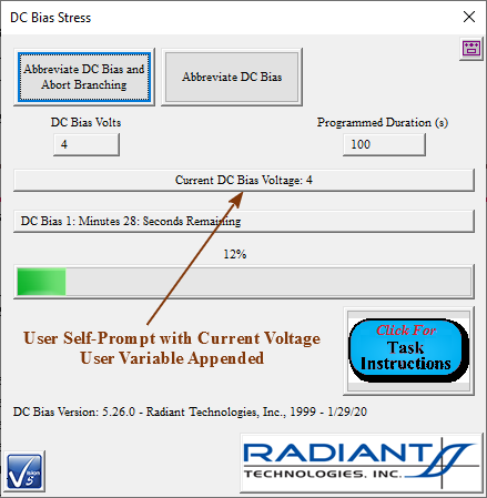
Most Tasks that present a dialog on execution include a field that can by preprogrammed by the experimenter to display a text message. The text message can often have a single User Variable appended to it so that the user can review the current state of the Task or other program element.
The figure shows the execution of a DC Bias Task with the current DC Bias voltage appended to the User Self-Prompt
 | |
|
A User Variable is an element on a variable-length list that is maintained by Vision. Each element on the list has a name, a type and a value. The list is primarily augmented by Tasks as they are accessed, each adding its own collection of User Variables.
Custom User Variables may also be added to the list by the user using the Make User Variable Task. The user can adjust the value of an User Variable using the Update User Variable Task. However most User Variables are maintained by the Tasks that created them and only Custom User Variables should be adjusted by the experimenter.
User Variables serve a variety of purposes including:
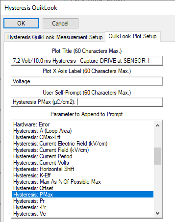
In the figure, the current value of Hysteresis PMax (µC/cm2) is to be appended to the User Self-Prompt on a Hysteresis Task Data Presentation dialog.
 | |
|
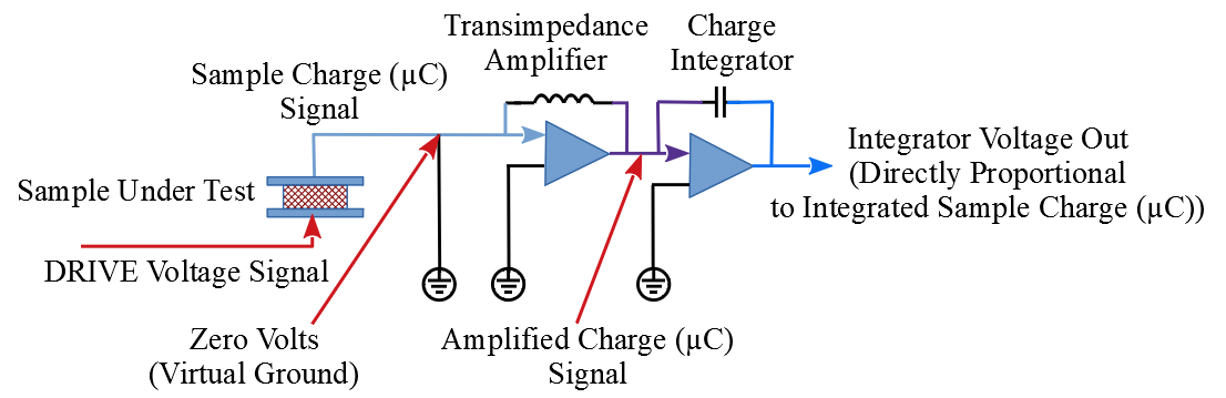
This is the name of the circuit that is used to capture and measure the charge from the Device-Under-Test (DUT) that enters the tester at the RETURN port. The circuit is referred to as "Virtual Ground" because the charge integrator that performs the measurement keeps the input electrically at, or very near, the tester's earth ground potential. This averts a host of noise and other issues as described in detail in the Tester Theory section.
 | |
|
Broadly, Vision is the Radiant Technologies, Inc. program that controls the Precision tester and other Radiant Technologies, Inc. instruments. More specifically, Vision is a framework that provides services to a variable list of semi-independent agents, known as Tasks, that do the work of Vision. Available Tasks are found, on Vision startup, and loaded into the TASK LIBRARY. A subset of the Tasks, as determined by each Tasks, is also loaded into the QuikLook menu.
Services provided by Vision to the Tasks include, but are not limited to:
| |
|
A Vision Data File (VDF) is a binary file exported by a data-collection Tasks - Measurement or Filter. The file is specific to the Task and is headed by the Task Name. Both configuration parameters and measured data are exported to the file. The Task can both write (export) and read the file. And data-collecting Task can be configured to import (read) the file on execution instead of performing a normal data-collecting execution.
Vision Data Files have a file extension of *.vis.
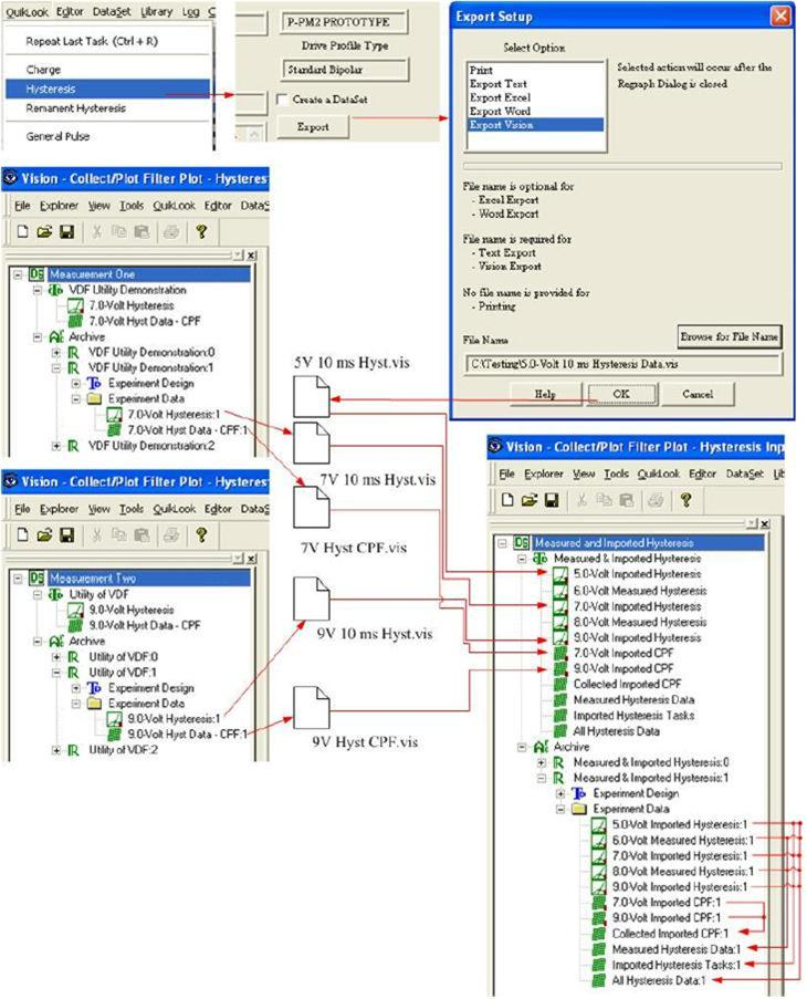
The purpose of this option was to allow data to be moved from anywhere in Vision into a new execution of the Task. In this way data from any number of disparate locations could be collected together with Filter applied to the collection. However, this is a tedious process. With the introduction of Data Mining and ETD Transfer, this option has been rendered obsolete. However, although the file formats have not been updated as Tasks are updated, the export/import option is still available and is extended to new Tasks as they are introduces.
The figure attempt to show the utility of the Vision Data File tool.
 | |
|
|
|
|
|
|
